
The Barnpartment PV System
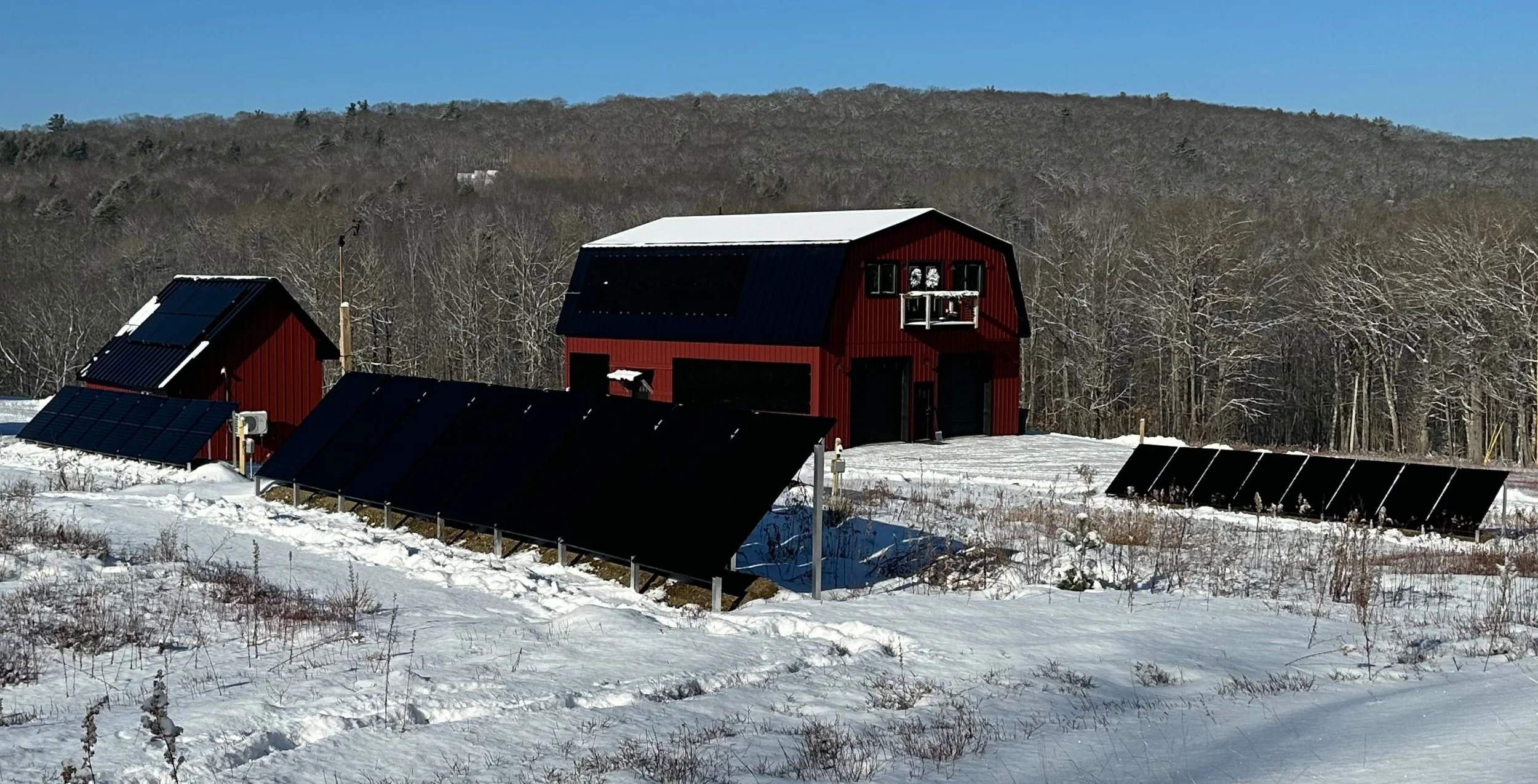
The larger building is the “Barnpartment”, a name my wife hates but I think both accurate and funny. The other building is my office, which has its own roof-mounted PV system. Also shown are 3 of our 4 ground mount strings. 4th is hidden from view by closest string in pic.
This is a long post. There, you’ve been warned. But it describes the PV system that powers our main building, so that takes a few words. If you want to learn more about that, proceed. If not, go read something else.
We have no connection to utility power despite the power lines running within about 150 feet of our house. We just didn’t want to be connected for reasons I’ll discuss in another post but given our reliance on our own systems for power, people are curious about how we produce electricity. I’m happy to say that our PV (solar electricity) systems easily supply us with all the energy we need, with room to spare. I’ll start describing these by describing the system in our main house, the “barnpartment”, and describe the systems in other buildings (I prefer to have a self-contained, fully autonomous system in each building) in separate posts.
The barnpartment system can provide up to 18,000 watts of power but we’ve never come close to needing that, even when we have three heat pumps running, we’re doing laundry, and cooking. I’ve tried turning on as many energy hog appliances as I could simultaneously to see what we could pull, and as I recall I maxed out at just over 12,000 watts. We’ll likely never see that in actual use because everything is designed for energy efficiency (see the appliance blog post) but it’s nice to know the equipment can handle whatever we throw at it. So, let’s get into the equipment list and descriptions for this main building system.
Inverters / Charge Controllers
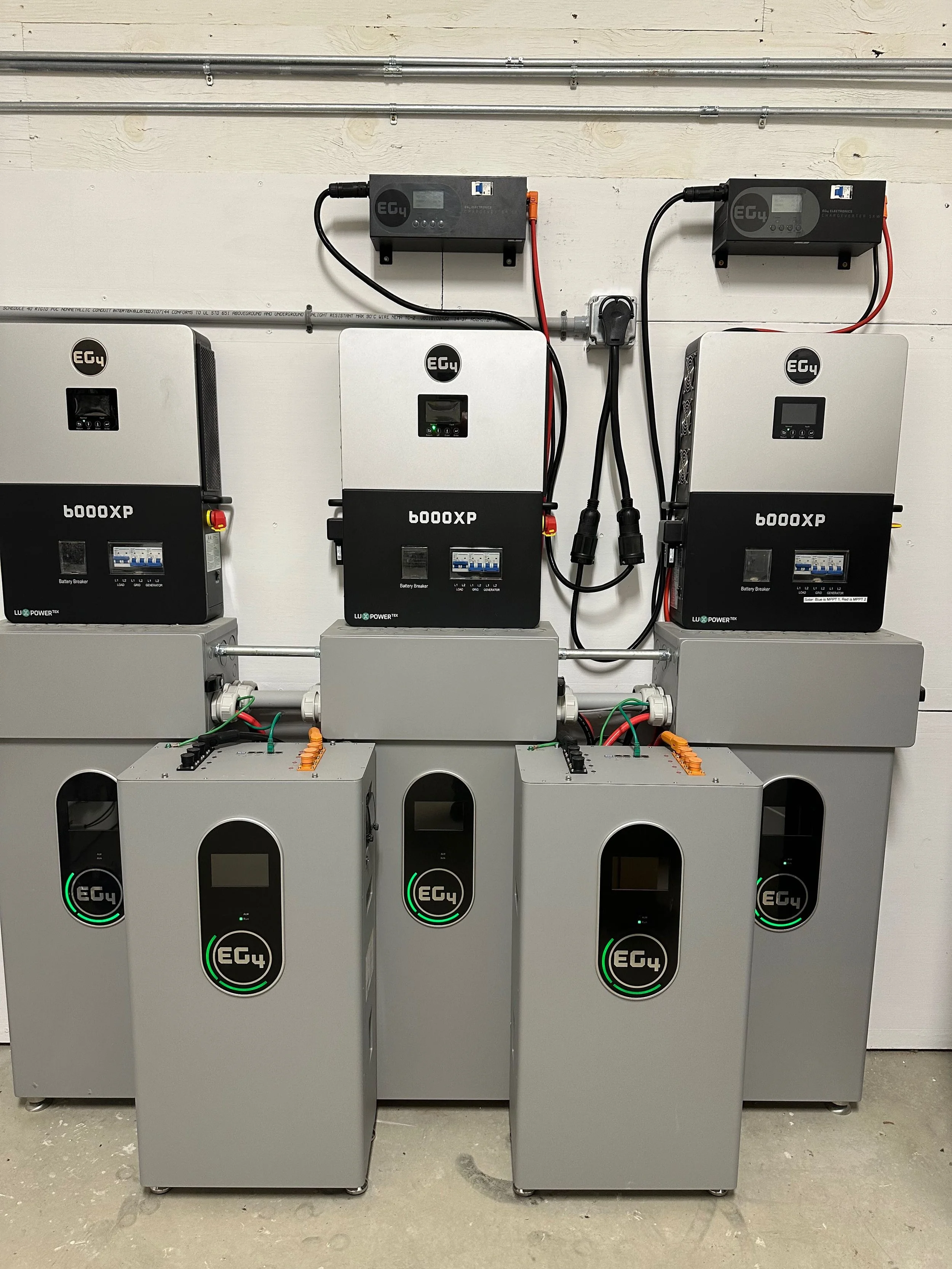
PV system for the barnpartment showing chargeverters at top, inverters/chargers, wiring boxes, and batteries. The Lynx distributor that connects the chargeverters to the batteries is mounted to the wall between the middle and right rear batteries.
I decided to use three 6 KW “All in One” (AIO) inverters (EG4 6000 XPs) instead of a single 18 KW inverter. An “All in One” just means that the device includes:
· An inverter (turns DC power into AC)
· A charge controller (the PV panel strings connect to this)
· A charger that allows a generator to be connected for times when you need to charge but there’s not enough solar power. I don’t use this, though, and accomplish this in a different way I’ll explain in another post)
I chose to use three smaller inverters instead of one larger one for two reasons:
· Having three inverters gives us some redundancy if one goes kaput. Given that we never use more than 12KW (and usually about half that even on heavy use days) we could cruise along just fine on two inverters while one is being repaired, even if we needed to reprogram one of them (there’s always a “master” unit that controls the other inverters, but any one of them can serve that role).
· Each 6000XP has two MPPT (charge controller / PV string) inputs, giving me a total of six. The comparable 18KW inverter from EG4 (the 18KPV) has only three inputs. My design required four, and I ended up adding another two that I discuss later in this post.
If I had to do it all over again, I’d still go with three smaller inverters instead of one larger one, and these 6 KW devices are just about right for us. I’ll discuss the MPPT (charge controller) inputs a bit later in this post.
Batteries
I initially installed three 280 amp hour (AH)/14.2 KWH batteries, and we could get through about 80-85% of winter with that 42.6 KWH of power (14.2 x 3). That would cover our typical needs for about two days with no additional charging (which almost never happens) and we could stretch it to three days if we tried. But we sometimes travel in winter, and I wanted some safety margin, so I soon added another two of these batteries for a total of 71 KWH (14.2 x 5) across the five batteries. With this battery capacity, we haven’t needed a generator since we got the last of our planned panels up in late 2024. Our lowest State of Charge (SOC) has been 15%.
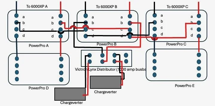
This is how the batteries and chargeverters are tied together using the Victron Lynx Distributor bus bar. Remember that the batteries are charged via PV through the 6000XP All-in-One inverters.
These are EG4 indoor “wall mount” Powerpro units. They sit on the concrete floor of the mechanical room, and I do not have them mounted to the wall as they’re in a dedicated mechanical room, there are no childrem around, and I’ve need to climb on top of them to tip them over. EG4 says up to 16 of them can be connected together. Wow! Who has THAT system?! Each of these batteries has a built-in 600-amp bus bar that allow for 4 positive and 4 negative connections. Each of three batteries connect to an inverter, and to the adjacent battery. Two of those first three batteries also connect to each of the two newer batteries. One of these batteries also connects to a 1000-amp bus bar (a Victron Lynx Distributor) that allows me to make use of an external charging source instead of a generator running through the inverters. That’s larger than I need but I really like the Lynx distributor as it includes fusing, so I use it instead of a slightly cheaper option. More info on the external charging (if/when needed) below.
These batteries have a Battery Management System built into them and it has worked well for me. It uses only passive balancing, but so far, the individual cells have stayed balanced. Recharging to 100% often really helps with that and I see no need for an active balancer or external BMS at this point for my system. The batteries also have a circuit breaker built into them, so I don’t need another one or a fuse between the battery and the inverter (which also has a circuit breaker for the battery input).
The Solar Panels
Solar panels are largely a commodity these days. Buy any decent brand sold by a reputable retailer and you’ll probably be fine. I went with Canadian Solar mono panels on the building itself and Hyperion bifacial panels for the first of our ground mount strings. I later added Longi bifacials when I added more panels (more on that below). Yes, I like the Hyperion panels a little better than the Longi panels but it’s mostly because of aesthetics and the fact that they melt snow modestly better. But the differences are miniscule and I wouldn’t advise anyone to fret over panel brands. Buy from a quality retailer and you should be fine.
I calculated a need for 13-14 KW of panels, and that proved to be just what we needed through our first winter. With that amount of solar generating capacity, we can power our loads and recharge enough to not need a generator except in the worst of weather, which was better than I expected. I decided to go with 400W panels largely because they’re a good balance of power vs. size. Panels get harder to lift and manage the larger they are, and I really like the physical size of a 400W panel. I did add more panels about a year after our initial install but they weren’t needed. See below for more on why I did it.
The big limitation for solar power is the voltage of the PV string. If you try to put too much power (amps x volts) through a solar charge controller it will just “clip” the power and nothing bad happens. But if you allow the voltage itself to exceed the limits of the charge controller, “magic smoke” appears and you fry your charge controller. This can happen instantly! When you connect panels together in series the voltage of the string is the sum of each panel’s voltage, and that’s what you must pay attention to. Voltage of solar panels increases as the temperature decreases so you need to plan for the coldest temperature your system will ever see, which usually occurs right at sunrise on a very cold, clear day. All this worked out to me having a maximum of 10 panels on a single string for the panels I selected, so I decided to put a 10-panel string on our gambrel roof, which was designed to match the exact angle of the sun at solar noon on the day of the winter solstice (67.2 degrees, at our latitude, and yes, I really did design the building with all that in mind). This 4KW string is the “main engine” string of our system. The steep angle also means that snow will come off within a couple of hours even after a big storm, once the sun comes out. If you live where it snows, think about the effect of that snow when you’re planning your system. Steeply angled panels are less likely to retain snow and can shed it quickly. Shallow angles don’t do either. The pitch of the roof is often the biggest problem with roof-mounted panels in snow country, as most roofs are shallower than 45 degrees (12/12 pitch). Snow covered panels don’t produce much, if any, power, so 45 degrees is my suggested minimum for roof-mounted panels for an off-grid system. Systems connected to a utility can get by with much shallower angles.
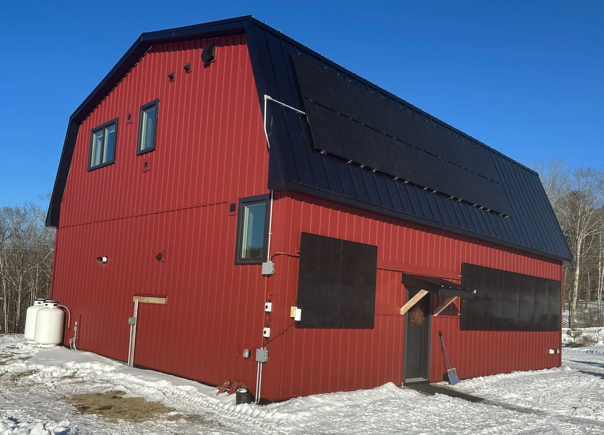
These are the building-mounted panels, both on the gambrel roof and on the side of the building. The propane tanks are for the radiant slab hydronic heating system for the garage and entry foyer. Now shown are three heat pumps on the other side of the building.
In addition to the gambrel roof string, I installed three additional strings of 8 panels each, for 3.2KW per string. I chose 8 instead of 10 panels largely due to space limitations. Two of these strings are bifacial panels on ground mounts, at 45 degrees. This is within a degree of our latitude so a very good “all purpose” angle that captures a decent amount of power all year while still being steep enough to shed a light snow within an hour or two after the sun comes out, and within a couple of days of sun if I don’t clear them at all (never happens – I’m obsessed with clearing them, but this might become important if we’re away, sick, or when we get less able one day). Bifacial panels add another 10-15% to the power harvested and they cost almost the same as a mono panel, so there’s no reason not to use them on a ground mount. I’ll talk about the ground mount system I used in another blog post.
The final string of “needed” panels also consists of 8 panels (3.2KW) but I decided to try a little experiment with these. They are mounted at 90 degrees (vertical) on the side of the building. Most people, including an experienced solar designer I know, thought this was a terrible idea. I heard, “They’ll hardly produce anything!” more than once, but I was convinced it would work, and I was not disappointed. During the worst of winter (November – January) there are days these panels are our best performers because:
· The angle difference from the sun in the worst of winter is just 23 degrees (90-67), so these are basically the same as panels mounted at 44 degrees, which people think is perfect (67-44) for our location. People just don’t consider that, surprisingly.
· These vertical panels never have snow on them! That’s a huge advantage in Maine, especially on days when I’m busy in the morning after a storm and can’t clear the other panels quickly (I hate when that happens – I really am obsessed about snow). But I often see these panels producing significant power even as I walk out to clear the other strings of snow, which happens perhaps 12 times or so each winter.
· When there’s snow on the ground you get an incredible amount of reflected light (called “albedo”). Vertical panels do a great job of capturing this light, and it contains an amazing amount of energy.
The vertical panels don’t perform as well as the other strings from about February – October but the difference isn’t huge, and the value they provide when we really need all the power we can capture more than makes up for the lower production at other times of the year. Those vertical panels are one of the best ideas I’ve had, and I installed them on the studio-guest house as well (that’s another post). All this adds up to 13.6 KW of panels at three different angles for the “core” (necessary) system. And again, that got us all through the winter of ’24-’25 with no use of a generator.
So, why did I install more panels?
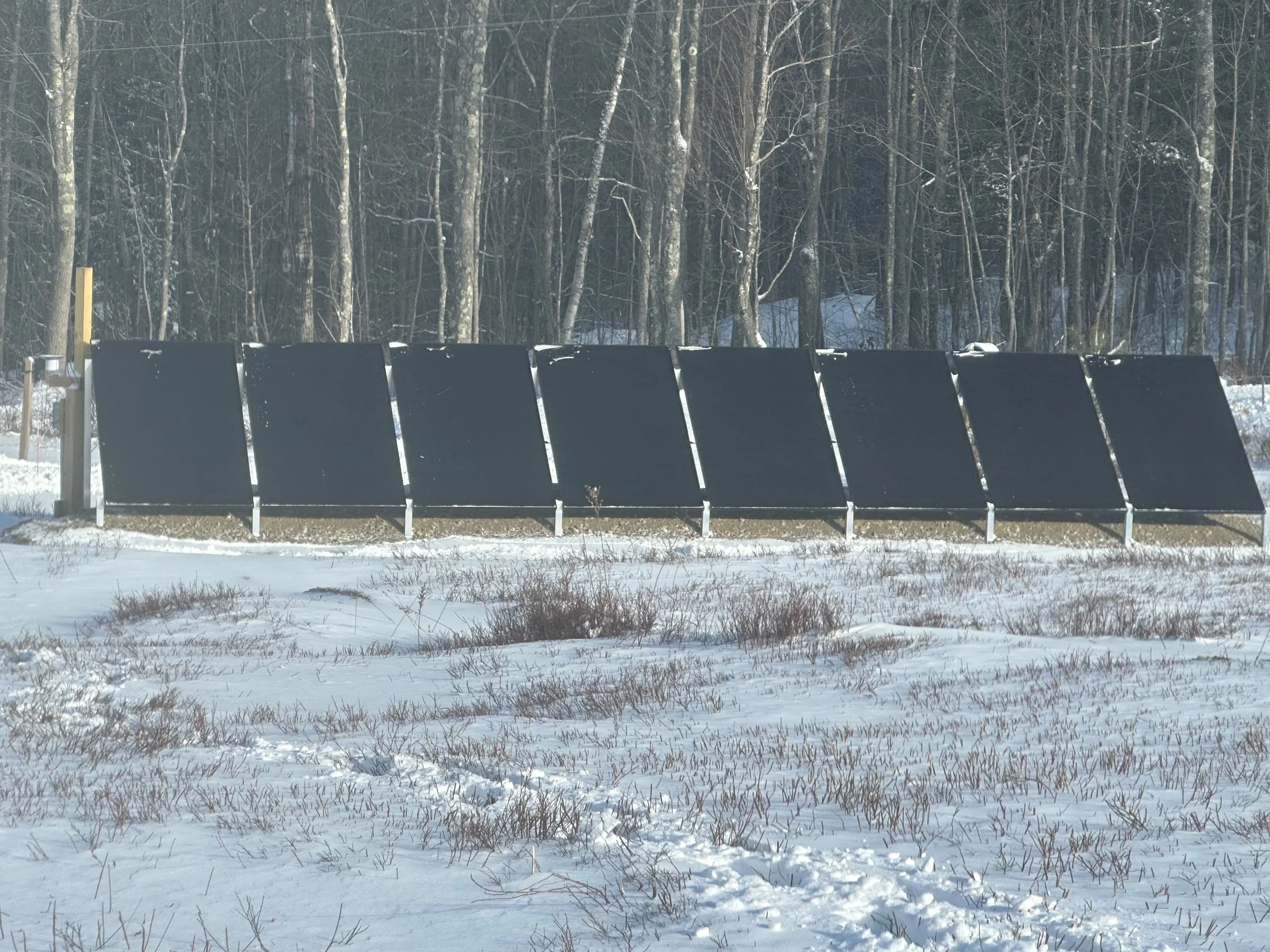
This is what each of our 4 ground mount strings look like. I used IntegraRack to mount these because we have so much ledge (surface bedrock). I like the IntetgraRack system but it does require some snow clearing, including snow that can quickly accumulate at the base.
The 13.6 KW of the original core system is what we “need”, but if we ever purchase an EV, we would be able to charge it only on very sunny days unless we add more panels. Also, I want to one day add an air-to-water heat pump to eliminate all or most of our propane use (for the garage and entry foyer radiant slab heat), when the price of those devices drops out of the nosebleed range in the US. We would need more PV to power that. I had originally planned on adding those extra panels only when we needed them, but the federal government decided to abruptly end the 30% tax credit on panels after 2025 (soooooo stupid of them!), so we decided to add two more strings of 3.2KW each before that happened, because we had two remaining MPPT inputs. I got them installed right before the weather turned bad in November, bringing us up to an even 20KW of panels today.
With this much energy now coming in, we don’t need to watch our energy use much at all, even during cloudy winter weather. It snowed lightly for much of the day today with only weak sun coming through but we still recharged back to 100%. And if we get even a modest amount of sun between storms, we’re still in good shape because we can recharge so quickly. If I had to do it all over again I’d install 20 KW of panels from the start, because they’re now very reasonably priced and having the ability to capture so much energy just makes life incredibly easy.
I also found a decent way to use that extra energy on sunny days. Until air-to-water heat pumps become reasonably priced, I installed a buffer tank with 6 KW of resistance heaters (simiilar to those used in a typical hot water heater) that allows us to heat water for the radiant slab with this excess energy. The thermal mass of the slab makes for an excellent “heat battery” so we pump this energy into it during those bright, sunny winter days. This means that the propane can sometimes stay off for days at a time during winter, especially for the garage (which we keep at about 60). This is not as efficient as a heat pump in terms of energy use, but it creates a nice savings in both energy and money because we use less propane, without the thousands it would cost for the air-to-water heat pump today. There’s a blog post or two about this system, here on the site.
The PV Combiner Boxes and SPDs
I’ll go into more detail in another post about the equipment I use near the PV panels, but let me first note that I transition from PV wire to 10 gauge (GA) THHN/THWN wire in a junction box near each string of panels because it’s so much easier to work with and you can fit much more of it into conduit compared to PV wire, which has a lot of insulation. This is a common practice and the only way I know of that makes sense, when it comes to running PV wiring through conduit for long stretches. Do not try that with PV wire.
I should also note that the term “combiner box” is often confusing because while it can be used to combine strings, many people (like me) don’t. It’s just what they call the box, which is designed to hold DC breakers and SPDs. You MUST use special DC breakers and it’s just plain stupid not to use SPDs because you WILL get surges from lightning.
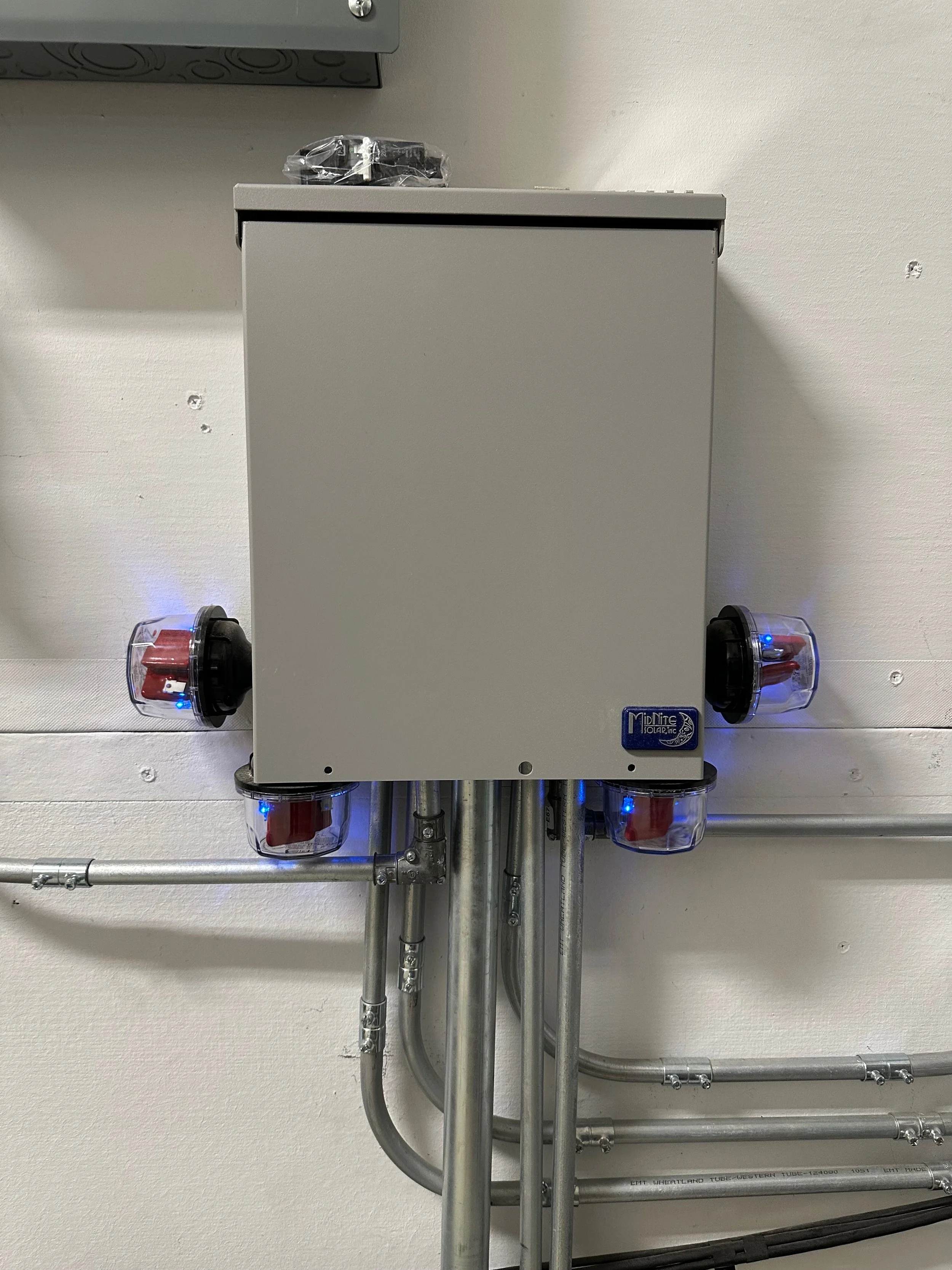
First combiner box with conduit and SPDs shown. Big conduit contains wires for 4 ground mount strings. Pic taken before I added another combiner box that looks like a sub panel to this one, for the 5th and 6th strings added in 2025.
The wiring for the gambrel and vertical strings on the side of the building come down the side of the building in conduit and then run underground along the edge (through conduit) before they come back up outside the mechanical room, where they enter in through the wall (again, in conduit). The ground mount wiring runs in conduit from each string / mount, down to the nearest ground mount to the house where they all enter a 1.5” conduit that runs under the driveway, and then under the slab for the length of the garage, into the mechanical room, where it pops up out of the floor. Code requires the use of metal conduit once you enter the building (no PVC for solar (DC) inside the house), so we transition from PVC on the outside and under the slab, to EMT once inside the building.
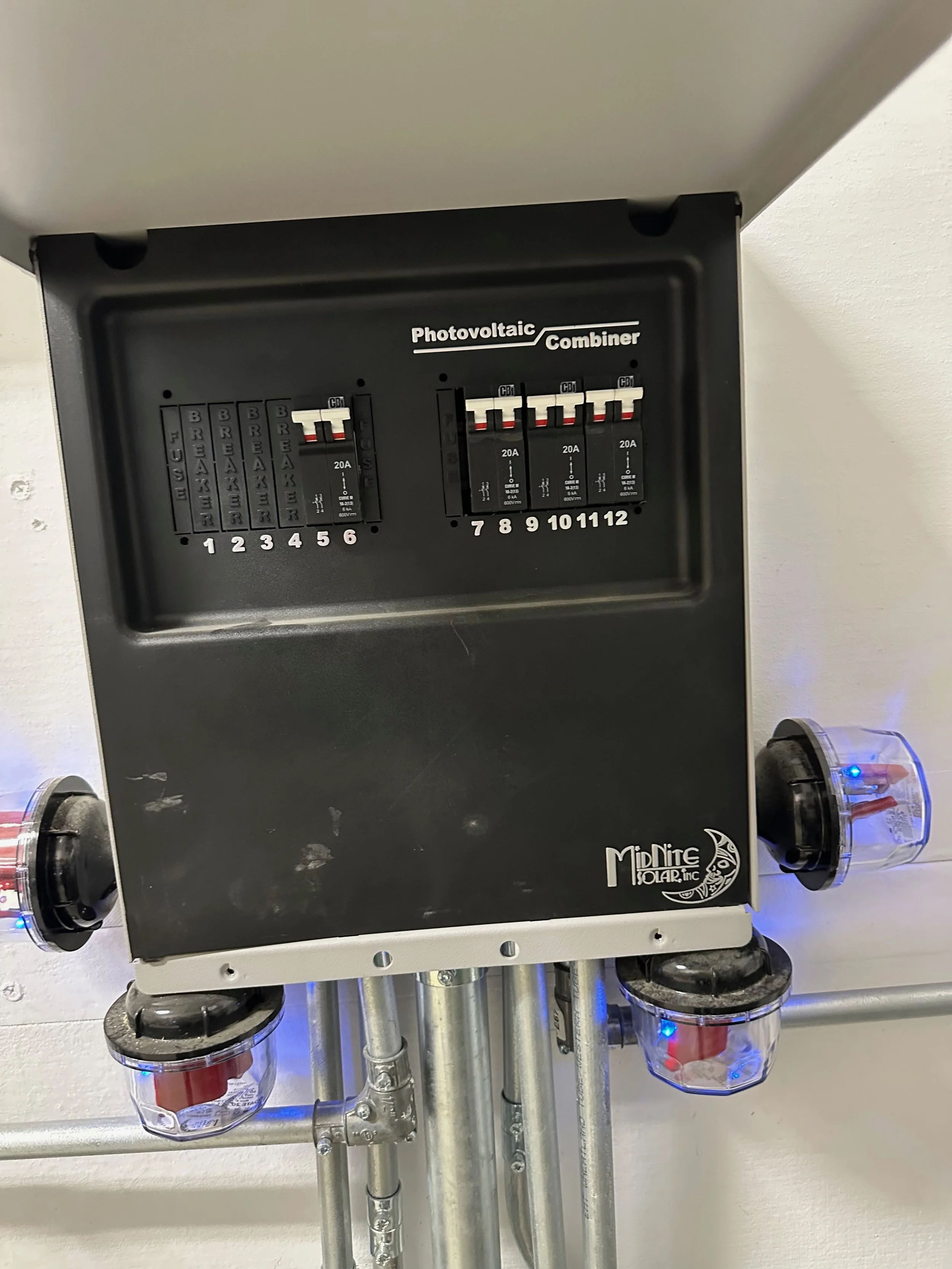
Same combiner box, with the cover raised to show the DC breakers for the first four strings. Picture taken before I added the other combner box to accommodate the 5th and 6th strings.
All six strings run through these conduits to the first, large Midnite Solar combiner box. The four initial strings connect to a 600V/20A DC breaker (one for each string) in this box, and each string is wired into its own Midnite Solar Surge Protection Device (SPD). The other two strings (the newer ground mounts) also run into this box because I ran the wiring for additional strings when we did the initial installation of the first four strings. I could fit them into this first box as far as DC breakers go but I’m out of space to easily mount SPDs on the side of that combiner box so I just run those two newer strings through the first combiner box without connecting to anything, and then through conduit to another, smaller combiner box. This allows me to install the two additional SPDs there along with DC breakers for those strings.
The wiring for each of these strings (still 10 GA) then runs through EMT conduit to big wiring boxes that sit between the batteries and the inverters (they’re specifically designed to do exactly this). Conduit is run between these boxes and two sets of wires plus a ground run to the two MPPT (solar charge controller) inputs on each inverter, which also has a rotary on/off switch for the MPPTs. It all makes for a clean-looking system that works well. By the way, the PVC conduit you see between those wiring boxes is for the AC wiring and communications cables, which is fine. The metal conduit contains the solar DC wiring.
Connecting the inverters to the main electrical panel
When I first built my multi-inverter system I wondered how to bring each inverter’s AC output together, but once you see how it’s done it’s very simple. You simply purchase a small electric panel (the kind usually sold to function as a sub panel) and bring each inverter’s AC output into a double pole (240V) breaker in that box, that is appropriately sized to handle the AC output of each inverter (40A, for each of my 6KW inverters). So, I have three 40A double pole breakers in this sub panel box, which is really functioning as an AC combiner box. I then run two appropriately sized hot wires, a neutral wire, and a ground from this panel over to an appropriately sized double pole (240V) breaker installed into the main electric panel. This safely combines the output of the three inverters and allows us to power anything we wish in the building. I suppose one could simply connect the output of the AC combiner “sub panel” box straight into the hot lugs of the main electric panel but I think it’s safer to use an appropriately sized breaker for this. Code may require it but I didn’t check because I wanted to do it anyway.
I should note here that you should have only ONE place in your entire system where you connect (bond) your neutral and ground. In a utility-connected system you do this where the power first enters the building but in an off-grid system it’s not quite the same and you have a little bit of flexibility. I complete this bond in a very conventional way, through use of the “green screw” in the main electrical panel that is used for most utility-connected systems. It works great, is safe, and a future electrician working on the system won’t be confused by me putting it somewhere else. And as I read it, this IS the place where the AC power first comes into “the system”, as most electricians (who are more familiar with utility-connected systems) view “the system”. The ground from the main panel then runs out to two ground rods, just as in a conventional, utility-connected system. I’ll talk more about the ground wires running in from the solar panels in another post. For now, just understand that you MUST run an earth grounding conductor along with your PV wires, and connect that to both the panel framing/mount and the internal grounding inside the house. You should NOT install separate ground rods at the panels themselves, even though code allows for this but does NOT require it. I’ll talk more about why it’s a bad idea in another post, but go look up ‘“ground loops” and why they’re bad, if your curious now.
I didn’t go into a lot of detail about wire sizes or calculating conduit fills here because it’s easier and safer to rely on a good app for this. I like the free online tools provided by the Southwire company (a major wire suppliera) as I find them easy to use and reliable.
What do I do when I need to use a generator?
We haven’t needed a generator for two winters now but it’s a terrible idea not to plan for one because when you need it, you need it NOW in most cases. So, plan for having a generator ready to go at all times if you’re off-grid! I keep a second one on hand (“Two is one, one is none” is a philosophy that can save your rear end).
You can certainly run appropriately sized wiring from a generator inlet box on the side of the house straight into the generator input that exists on most inverters. But most inverters simply pass generator power straight through to the loads when current is detected on the generator input circuit, and generator power is notoriously “dirty” (low quality in ways I won’t get into here) unless you invest in an inverter generator. Those devices are much more expensive than a “regular” generator and typically deliver much less power unless you spend huge sums for a large one. I don’t want to send dirty power through to my loads, and I don’t want to listen to a generator for any longer than I need to, so I want more power than all but the most expensive inverter generators can deliver. So, what do I do?
Enter the “chargeverter”. This is a device that can take very dirty AC generator power as an input and clean it up to very clean power DC power that can be used to recharge batteries quickly. It all connects like this:
· I use a large 13KW “contractor grade” generator that can put out 10KW continuously, for hours. These can be purchased for under $1500 (less than half the price of an inverter generator that produces perhaps 2/3 as much power, as I write this) but they produce dirty power. It has a 50-amp 240V output on it, so I connect that to a 50-amp generator input on the side of the house.
· From the generator input I run 6 GA wire (through conduit) to a 50-amp receptacle like the kind you would see for an electric stove, mounted on the wall of the mechanical room, just above my inverters.
· Into that 50-amp receptacle I plug in a “spitter” adapter that converts the single 50-amp receptacle into TWO 30-amp receptacles.
· The chargeverter is designed to plug into these 30-amp receptacles, so I plug TWO chargerverters into this splitter/adapter.
· Remember the Victron Lynx 1000-amp bus bar I mentioned earlier? This is why it exists. Each of the chargeverters are connected to this bus bar, as are the batteries for my system. This means that I never pass dirty generator power through to my AC loads or my batteries, or even into the inverter. Instead, my generator power goes only to the chargeverters, and it simply recharges the batteries. All power supplied to the inverters is coming from the batteries only (and PV, of course) but never from the generator, directly.
You can see the chargeverters in the image at the top of this post.
I set each chargeverter to charge at about 75 amps instead of its full 100 amp capability because this gives me a full 150 amps of charging power while limiting the generator to about 80% of its max continuous rated output, which is where I try to run generators to extend their life.
This system works great when we do need to use it, but I’m very happy it hasn’t been needed for so long.
Wrap up
This system works incredibly well. The only real complaints I have are 1) the 6000XP produces an incredible amount of fan noise (think large hives of bees) especially when the sun is shining brightly and its producing a lot of power, and 2) EG4 continues to have some annoyances (not mission critical, but annoying) with its firmware that need to be addressed, including a setting in the app that wrongly lowers the PV charging down to almost nothing if you try to change certain parameters. They’re aware of the problem but just haven’t bothered to fix it, which annoys me to no end. I’ve remembered to never adjust that, and frankly I don’t update my EG4 firmware during winter because I don’t want to take the risk. But the inverters sit in a very well sound-insulated mechanical room, so we don’t hear the “angry bees” unless we go in there, and I’ve learned to avoid changing that one PV charging setting.
All in all, I’m happy enough with my EG4 equipment, especially the batteries. I don’t like it quite as well as my Victron gear in other buildings, but the price point is much easier on the wallet, and for a large system, that can really matter. I’m not at all unhappy with this equipment, and I hope it lasts for at least 10 years, if not more. Time will tell, but so far, so good!